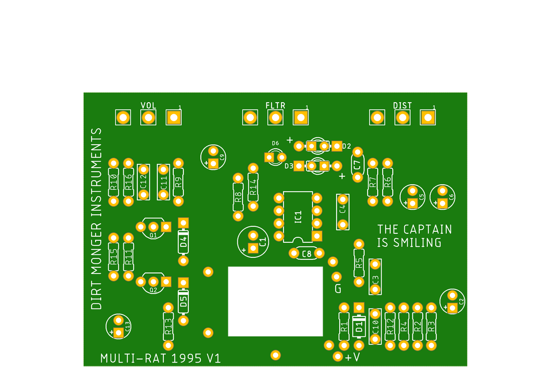
Multi-RAT 1995 1 to 1 drop in PCB
Share
TLDR: I designed a 1 to 1 RAT PCB based on the 1995 Multi-RAT PCB. It sounds identical and more importantly doesn't produce parasitic osciallation like most RAT clones on the market. This PCB can be used in the RAT 2 enclosure as a drop in replacement.
Does anyone actually need another RAT clone? Not really, I think the RAT has been cloned just as much as the tube screamer which has been cloned to ad nauseum.
Does anyone need a RAT clone that is a 1 to 1 drop in for the RAT 2 enclosure? Absolutely.
I've been wanting to do this for a while, several years ago I realized the PCB layout of the RAT was done in a specific way to maintain signal integrity. I don't have the equipment to scientifically prove this theory through EMF testing so trying it out is the next best thing. As D Boon once said, the knowin' is in the doin'.
I've noticed that every RAT clone I've ever played or built has inherent oscillation. when the distortion and volume are maxed out it only takes turning the filter up to about 11 o clock to produce oscillation, however on the original RAT these oscillations don't occur. From what I can tell this stems from the parts placement on the PCB, while it may be an overlooked part of the design it's really the only factor that makes sense.
You're probably thinking, well yeah but I wouldn't use those settings anyway, who maxes out a RAT? This ain't an HM-2. The maxed out settings aren't the point, oscillation at extreme settings are a sign of an EMF field producing undesired oscillation on components which can be corrected by moving these fields away from each other. Overall this will make the design sound better, no matter what the settings.
The RAT 2 that I own uses standard components, 5% carbon resistors, 20% electrolyic capacitors, 5% ceramic and mylar capacitors and standard quality transistors, diodes and opamp. There's really no mojo* parts that I can tell, so why does it not oscillate? I think it has to do with the well thought out PCB layout coupling certain components to avoid parasitic oscillation.
At first glance the Multi-RAT PCB 1995 revision that I fashioned this design after doesn't look like a well thought out design at all, you've got parts spread out all over the place with lots of room in between but on closer examination it makes a lot of sense.
For starters the power circuit is far away from most of the audio circuit, or at least the part of the circuit susceptible to parasitic oscillations. Same goes for the LED indicator circuit, this is mostly out of the way from the audio components. There are very few long trace runs also besides the power and ground traces which are pretty much impossible to get around with a 1 sided PCB.
On the topic of traces, they are almost identical to the original but with a wider width for signal integrity. The original PCB only had traces on one side and no PCB planes at all which I tried to keep the same.
I called this replacement PCB a 1 to 1 which isn't exactly true, but hey that marketing for ya. People hear with their eyes. For starters you can't get the pots that were used when these were being built. They are a 24mm top down mounted pot with lugs that point towards the shaft, these are hard to find, expensive and not really necessary since they don't play a big role in the overall circuit characteristics and modern substitutes are easily available. With that in mind these pots have been updated with 16mm bottom mount pots.
As a result of the height difference between the original pots and updated ones, the 2PDT footswitch cutout has been changed to accommodate the entire switch to passthrough the PCB for height requirements. the supply pins to connect the footswitch lugs to the PCB have been kept the same so a footswitch can be installed just like the original.
The RAT PCB layout has changed over the years but I haven't been fortunate enough to play all the revisions and can't say whether parasitic oscillation occurs on any other PCB revisions. With the resell price on vintage RAT's being way out in the blues lawyer territory I don't know if I'll ever get the chance to dissect an older PCB, time will tell.
* for the record I hate the term mojo, it's used by forum trolls in love with NOS rainbow fish caps and Mullard transistors with no scientific basis only their "golden ears" as proof. People hear with their eyes and nostalgia is the greatest human weakness, admittedly old parts look pretty cool even though they seldom if ever offer better sonic properties. Unfortunately mojo is the only term that makes sense here when referring to just how standard and unassuming the RAT components truly are and the whole is greater than the sum of its parts in this case. I'm no neologist so if you can think of a better term then let's get it crackin'. Rant completed.


